Superbooth 2021: Doepfer Introducing 5 New Eurorack Modules
Ahead of Superbooth 2021, scheduled for Sept 15-18 in Berlin, Doepfer has introduced five new Eurorack modules, along with a new case that features a keyboard built into the lid.
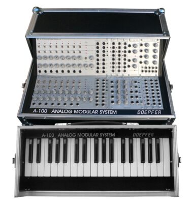
The Doepfer 100PB is a Eurorack case with a keyboard built into the lid. It features 37 keys, a MIDI interface with 3.5 mm stereo jack socket, power supply (1200mA) and two bus boards.
The A-126-2 Frequency Shifter is a fully analog frequency shifter for audio signals.
A frequency shifter is an audio processing unit that shifts each frequency of the incoming audio signal by the same frequency. If the shifting frequency is e.g. 200Hz an incoming audio frequency of 1000 Hz becomes 1200 Hz, 2000Hz becomes 2200 Hz, 3000 Hz becomes 3200 Hz and so on.
Because frequency shifting adds a fixed frequency to the source signal, it results in very different results than pitch shifting or slowing down/speeding up sounds.
The A-138f Dual 3-way crossfader contains two identical crossfaders, with three inputs and one output each.
Three different signals are connected to the inputs A, B and C. In the ccw position of the corresponding control only signal A appears at the output. Between ccw and center position a mix of the signals A and B appears at the output. In the center position only signal B appears at the output. Between center and cw position a mix of signals B and C appears at the output. In the cw position only signal C appears at the output.
The module is DC coupled and can be used for both audio and control voltage processing.
The A-149-4 Quad Random Voltage Source generates four triggered random voltages, which meet the criteria choosen by several controls.
It features controls for the criteria selection:
- Octave range (manual control “Oct.”): this parameter defines how many octaves are covered by the random voltages (0 … +5V, with “Oct.” control fully CCW only 0V are generated)
- Grid (6 illuminated radio buttons): this parameter defines the grid of the random voltages:
- Octaves (Oct)
- Octaves + Quin (Quint)
- Chords
- Scale
- Semitones
- continuous (i.e. stepless)
- Minor / Major (2 illuminated radio buttons): this parameter defines in case of chords or scales if they are minor or major. For all other grids this parameter has no meaning
- Sixth / Seventh (2 illuminated separate buttons): these parameters defines if the sixth or seventh is added. Valid only if Oct, Quint, Chord or Scale is chosen as grid.
The A-179-2 Light Controlled Voltage Source II can be used to convert different illumination intensities into corresponding analog voltages and a gate signal derived from the analog voltage.
A light sensitive resistor (LDR) converts the illumination of the internal light sensor into a corresponding analog control voltage. The internal sensor is located at the front panel. Instead of the internal sensor a remote sensor can be connected via a standard patch cable to the module (ext.Sens. socket). An external sensor with a 2 m patch cable (A-100C200) is included. The external sensor is mounted on a small pc board which is equipped also with a 3.5 mm jack socket.
One can choose between passive control by covering/shading the sensor via hand or body, or active control by using e.g. a pocket lamp or flashlight. For this two versions of output voltages are available (CV Out + und CV Out -).
The Doepfer A-182-4 Dual Rotary Switches is a passive module that contains two mechanical rotary switches, with 4 positions each.
According to the position of the control knob socket 1, 2, 3 or 4 is connected to the common socket C. As the module is fully passive it works bidirectional, i.e. the sockets 1…4 can be inputs and then C is the output. The other way round C can be the input and the sockets 1…4 are the outputs.
By means of an internal jumper the terminals C of both switches can be connected. That way the module can be used as kind of a miniature 4×4 matrix. Rotary switch A is e.g. used to select one of the four sockets 1…4 as input and this signal is sent to one of the four sockets 1…4 of switch B. Visit the Doepfer site for details.


